
Trailer Wiring Guide: How to Wire Your Trailer for Safety and Efficiency
Table of Contents
1. Common Types of Trailer Connectors
2. Trailer Wiring Diagrams: Color Codes and Functions
3. Tools and Materials You'll Need
5. Troubleshooting Common Trailer Wiring Issues
C. Wiring Converters and Inverters
D. How To Find The Right Wire Gauge
7. Conclusion
What is Trailer Wiring?
RecPro has worked in the RV and trailer industry for nearly two decades, so we know much about trailer wiring. But what is it? Trailer wiring, or trailer cable, isn't hard to understand. Essentially, trailer wiring supplies power to the lights and brakes on a trailer. Trailer wiring can also refer to the electrical systems found in RVs and campers, which supply power to various appliances and accessories.
In this article, we'll go over all there is to know about trailer wiring, including different types of trailer plugs and the different color wires they have, several methods for installing trailer wiring on your trailer and tow vehicle, and how to identify and fix common problems. We'll also go in-depth on RV wiring, including a close look at the 12v DC and 120v AC electrical systems, how to wire your RV converters and inverters, and how to find the right wire gauge.
Let's begin!
Common Types of Trailer Connectors
There are several varieties of trailer plugs or connectors to explore. These connectors can come in various shapes, such as flat, round, and square, with four to seven wires.
What's so important about the number of wires on a trailer plug? Usually, the more wires a trailer has, the more functions it offers that can be controlled by the tow vehicle. Here are some common trailer wiring configurations you'll find on a trailer:
Four-Way Flat Trailer Connector
The 4-way connector is the most common of connector types for light-duty trailers. As you might expect, it provides a four-wire connection for operating the trailer turn signals, brake lights, taillights, and a ground for the circuit.
Five-Way Round or Flat Trailer Connector
While very similar to the four-way flat, the 5-way flat connector has four pin connections in addition to one socket connection, while the five-way round uses socket connections entirely. In either case, a five-way trailer connector adds another wire, allowing travelers to use an extra trailer function such as electric brakes or trailer reverse lights. Five-way connectors are commonly found on boat trailers.
Six-Way Square or Round Trailer Connector
A six-way trailer connector is similar to a five-way in function, as it retains the additional wire for using extra trailer features. However, the six-way trailer connector also adds another wire dedicated solely to 12-volt power to allow travelers to charge a 12v battery, which is why it is commonly found on small campers. The 6-way connector is most commonly found in round and square shapes.
Seven-Way Trailer Connector
This type of trailer wiring connector commonly has flat blade pins in a circle. It is also known as an RV-style connector but can also be found with round pins. 7-way round connectors are most commonly found on trailers equipped with two or more axles, some of which include enclosed trailers, large campers, RVs, and heavy-duty trailers. You can find an example of a 7-way trailer connector here.
7-way trailer connectors most often come in one of three varieties: Standard Round, Traditional Blade connector, and SAE J2863 configuration. Traditional Blade and Standard Round 7-ways are often used on campers, travel trailers, and 5th wheel trailers, while SAE configuration 7-ways are usually used on gooseneck trailers, cargo trailers, utility trailers, and equipment trailers. There are some slight differences in the wiring colors, which will be noted below.
Trailer Wiring Diagrams: Color Codes and Functions
Four-Way Trailer Connector Color Codes
 |
|
Five-Way Trailer Connector Color Codes
 |
|
Six-Way Trailer Connector Color Codes
 |
|
Seven-Way Round Trailer Connector Color Codes
 |
|
Seven-Way Traditional Blade Trailer Connector Color Codes
 |
|
Seven-Way SAE J2863 Trailer Connector Color Codes
 |
|
Tools and Materials You'll Need
Essential Tools
The tools you will need to install, repair, or maintain your trailer wiring system vary widely depending on what you intend to do. For example, all you may need is a replacement light bulb to repair your trailer lights. In contrast, a full trailer wire installation may require tools like a wire stripper.
Some of the tools you may need can include but are not limited to:
- 12v battery
- Extra wire
- Continuity tester
- Dowel
- Dielectric grease
- Electrical contact cleaner
- Electrical tape
- Light bulbs
- Jumper cable
- Drill
- Nut driver
- Nuts, bolts, or screws
- Sandpaper
- Screwdriver
- Wire fasteners
- Wire stripper
- Wiring kit
- Tow vehicle tester
How To Wire A Trailer
Step 1: Preparing Your Vehicle and Trailer
First, inspect your vehicle and your trailer to determine what kind of installation you'll need for your towing setup. Most modern vehicles will already have a factory-installed trailer wiring harness or feature wiring plugs to help install trailer wiring.
Thoroughly read the owner's manual of your vehicle to determine if it already has trailer wiring or wiring plugs equipped and where they are located.
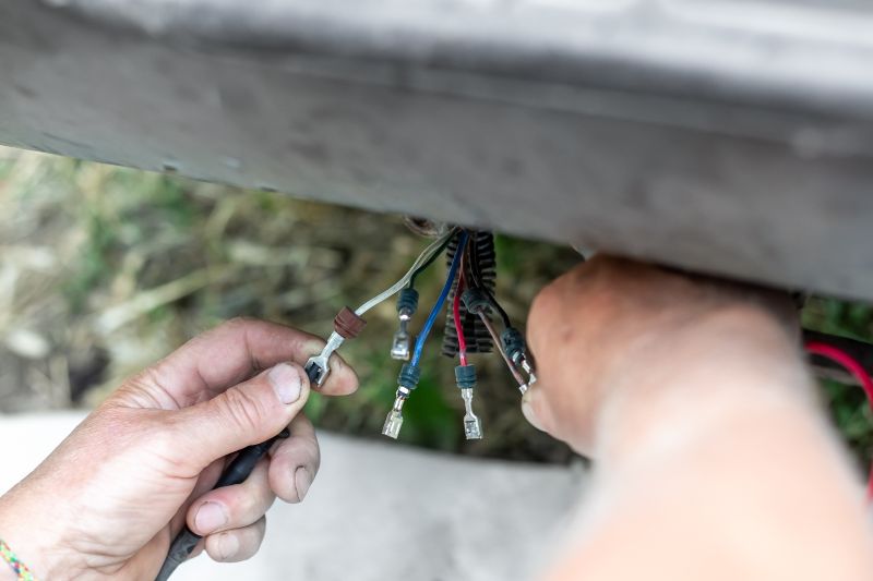
Step 2: Installing the Wiring Harness on Your Vehicle
If your vehicle does not have factory-installed trailer wiring, you must install the wire harness yourself. Thankfully, this is a fairly simple process. You can usually access your vehicle's wiring system near the rear of your vehicle, behind the taillights.
Before you begin splicing any wires or making any connections, use a circuit tester to confirm what each wire does for each function (brake lights, left turn signal, right turn signal, etc). This way, you can ensure you're connecting the vehicle wire harness to the right wires.
Before making any wire connections, you should connect the white ground wire to the vehicle. The white ground wire should be connected to a bare metal surface on the vehicle frame that is clean of dirt or debris.
Sandpaper can help you get a good, clean bare metal spot for a strong connection. Once you've connected the ground wire, apply some dielectric grease to help prevent corrosion.

Plug-In Style Wiring Harness
Some vehicles may come with T-connectors, allowing you to simply plug the wires from the wiring harness in without cutting or splicing. Using a wiring adapter, these T-connectors can also be expanded to 5-way, 6-way, and 7-way trailer connectors.
Clamp-On Style Wiring Harness
Clamp-on style wire harnesses are pretty unique. They are designed to clamp onto your vehicle's wiring using zero-contact interface sensors that can detect current as it travels through your vehicle wiring.
However, clamp-on-style harnesses don't draw power from the vehicle's wiring, so you'll need to run the hot wire up to your vehicle's battery to supply it with the necessary power.
Splice-In Style Wiring Harness
People often feel a bit nervous about splicing wires. Still, it's a very safe and straightforward method for connecting your trailer wire harness.
However, it is less convenient than other harness styles. Once you've confirmed the functions of your vehicle wires, you can connect your wire harness in one of three ways:

Soldering: This method provides the strongest and most reliable connection for your wires. Simply solder the wires together using a soldering gun and some solder, and protect the connection with heat shrink tubing.

Butt Connectors: If you don't feel confident about soldering your wires or lack the needed tools for it, then using heat shrink butt connectors and a heat gun is the next best option.

Quick Splice Connectors: Quick splice connectors are the easiest and fastest way to connect your wires. A quick splice connector clamps down on the wires and forces a metal tab into them, which connects the circuit.
However, remember that while these connectors may be the fastest and easiest method, they are not as reliable as the above mentioned methods.
Other Notes
The electrical system of some vehicles may not be able to handle the amp draw of the trailer lights. If this is your situation, you must run a power wire from the vehicle battery to the harness.
Don't leave your connector dangling, as this could cause damage to it as you travel. If your connector is under your vehicle, use a mounting bracket to keep it secure.
You should use a small amount of electrical grease on all electrical connections, including the plug itself. This will help prevent corrosion, especially from elements such as salt water.
Step 3: Connecting the Wiring Harness to the Trailer
Installing a wire harness on your trailer should be simpler than installing one on your tow vehicle. Before making any connections, you should connect the ground wire to a clean, bare metal patch on the trailer frame.
Ideally, each component on your trailer should have a ground, as this will decrease the likelihood of a grounding issue, which is the most common issue people run into when wiring their trailer. Making sure the wiring is properly grounded on your trailer, especially for RVs and campers, is very important.
Improper grounding can result in what's known as "hot skin", which is when the exterior metal surfaces of your trailer, RV, or camper become electrified as a result of faults or improper grounding in the electrical system. In other words, improper grounding can result in your trailer becoming electrified and will shock you if you touch it.
Once the ground wire is secure, you can start running the rest of the wire along the frame of your trailer to your taillights, ensuring the connector plug can still extend past the tongue of the trailer by 2 to 3 feet.
If possible, feed the wires through the hollow parts of your trailer frame to give them a little extra protection. If you have loose wiring, secure it using zip ties or wire clips so they don't chafe or catch on any trailer components.
Next comes connecting the wires to the components of your trailer. This will depend largely on the components of your trailer and the type of wiring harness you are using (7-way, 6-way, etc).
In general, the white wire will be the ground wire and should connect to the trailer frame, the yellow wire will be for the left turn signal and brake light, the green wire will be for the right turn signal and brake light, and the brown wire will connect to the taillights on both sides.
Refer to the "Trailer Wiring Color Codes and Functions" segment above to see what components each of your wires should connect to.
Step 4: Testing the Connections
Once the wiring on your trailer and your vehicle is set up, you can test the connections and functions. Connect the trailer and tow vehicle using the wire harness plugs, then turn the tow vehicle on.
Check to ensure the running lights on the trailer turn on, then start testing each trailer function, starting with the brake lights, the left and right turn signals, etc. If all connections and functions are working properly, then congratulations, you're all done!
Troubleshooting Common Trailer Wiring Issues
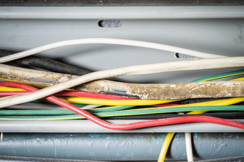
Identifying Wiring Problems
Identifying a wiring issue is easy. If a light doesn't turn on, then there's an issue. Figuring out what's causing the issue is the more challenging, although it doesn't need to be. You should always inspect your trailer lights and wiring before and after traveling, even if you only go a short distance. Look for signs of corrosion or damage on the wires and the connectors.
If you find signs of corrosion, clean the area with a wire brush or electrical contact cleaner, then apply some dielectric grease to prevent further corrosion. If you find damaged wires or connections, such as bent pins or debris in the wire plug, replace or repair them immediately.
Fixing Grounding Issues
Test each light to make sure it works. If you find a light that doesn't turn on, take a look at the lighting element, as you may only need to replace a burnt-out bulb. Suppose you've verified that the light bulbs are in good condition and that damage, debris, or corrosion does not appear to interfere with the wiring and wire harness. In that case, you likely have a grounding issue.
A poor ground connection is one of the most common problems regarding trailer wiring. Thankfully, it's an easy fix! Disconnect the ground connection and clean the lead and the area it was attached to. Then, reattach the ground connection, ensuring it has a clean and tight connection that contacts bare metal. Afterward, a small amount of dielectric grease is applied to prevent corrosion.
If a problem persists, it may be in the wiring itself. Check the entire length of the wire that may be causing the issue, such as the brown wire for faulty running lights for any damage or breaks. If there is no damage, use a multimeter to test the wire for shorts. Don't forget to check the connections on the trailer component itself. Once you've found the issue, repair or replace the faulty wire. You can read more about trailer and RV electrical standards and safety here.
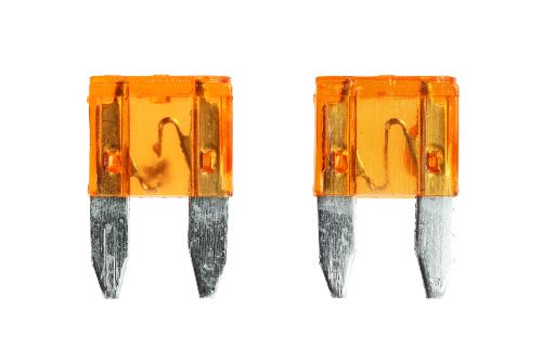
Addressing Blown Fuses
Trailers come with many different types of wiring harnesses. Some wiring harnesses on the market may feature a small converter with a couple of fuses. There are several reasons why a fuse might blow, such as wear, harsh environmental conditions, and power surges.
Often, this is a simple repair where you only need to pull out the blown fuse and slap in a new one. But, if your fuses continue to blow repeatedly, the issue may lie elsewhere. If your trailer is drawing too many amps and exceeds the limit for your converter, the fuse will blow.
You'll need to examine the components of your trailer and determine what is drawing enough power to blow your converter fuses to further diagnose the problem, whether it's a short in the system, an improperly wired appliance, or a poor ground connection.
A blown fuse may be the cause of a light not functioning, even if the lightbulbs, connectors, and wiring are in good condition. So, if you have a trailer wire harness equipped with a converter, check the fuses periodically for signs of damage or wear and replace them as needed. It may also be a good idea to keep a few spare fuses in your tow vehicle, just in case you need to make a roadside repair.
Camper and RV Wiring
When most people think of a trailer, they probably think of something like a boat, horse trailer, or flatbed trailer often used for hauling junk and other stuff around. However, the term "trailer" applies to more than just those examples. In fact, on many occasions, people use the term "trailer" to refer to different types of trailers, such as recreational vehicles, such as campers, RVs, toy haulers, and travel trailers.
While the typical light functions of these kinds of trailers are the same, such as the brake lights and turn signals, the interior wiring system of an RV or camper can be far more complicated than simple trailer plug wiring. Most camper-type trailers will, at the very least, have their own dedicated 12v power system that is separate from the tow vehicle and the trailer.
These separate systems, which also use 12v batteries, aren't used to run the trailer lights but are instead used to power appliances on the camper, such as an awning or speakers. RVs can get even more complex, as they not only have a dedicated 12v DC power system and their own 12v batteries but also another system for connecting to 120/240v AC power, or "shore power."
With these additional electrical systems, it's easy to see how wiring a camper or RV can quickly get very complicated, confusing, and messy, so we'll try to stick to the bare basics in this guide.
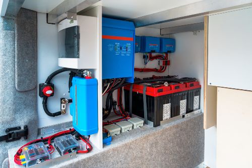
The 12v DC System
The 12v system in a camper or RV is used for a wide range of appliances and accessories, anything from speakers to refrigerators. But, instead of listing off every possible thing you could connect to 12v power, we'll just refer to them as appliances.
Let's give you a rundown of a basic 12v DC electrical system you might find in the average RV or camper. We'll start with the battery, or batteries in some cases.
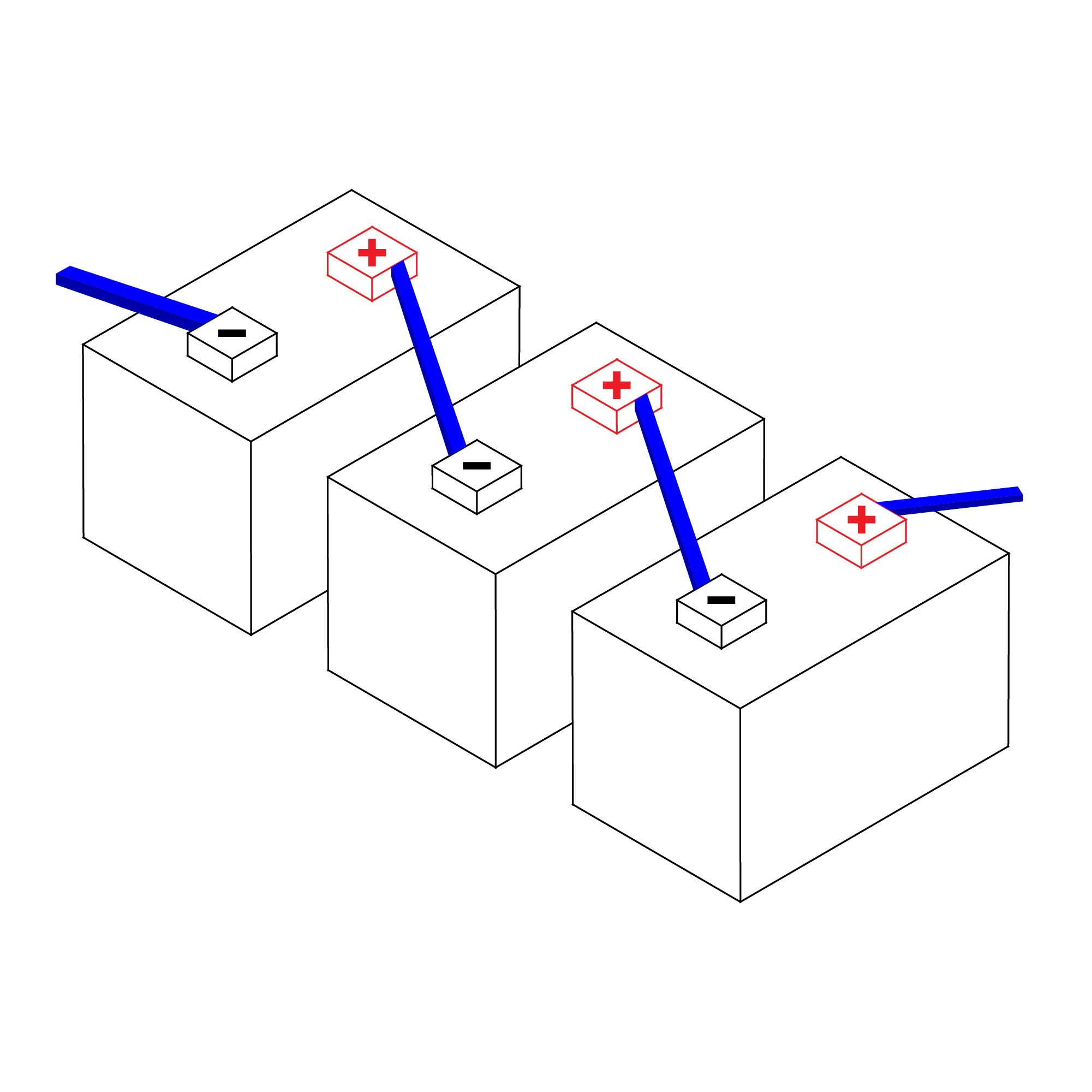
Wired In Parallel
The 12v system is powered by a 12v DC battery or a "battery bank," where the camper or RV is outfitted with multiple 12v batteries wired in parallel. "Wired in parallel" is a term that simply means the positive terminal of one battery is connected to the positive terminal of another battery, with the negative terminals of each battery being connected together as well.
The advantage of this setup is that it gives you the same voltage but increases the amperage. For example, two 12v DC batteries with an amperage rating of 10 amp hours wired together in parallel would give you 12 volts and 20 amp hours.
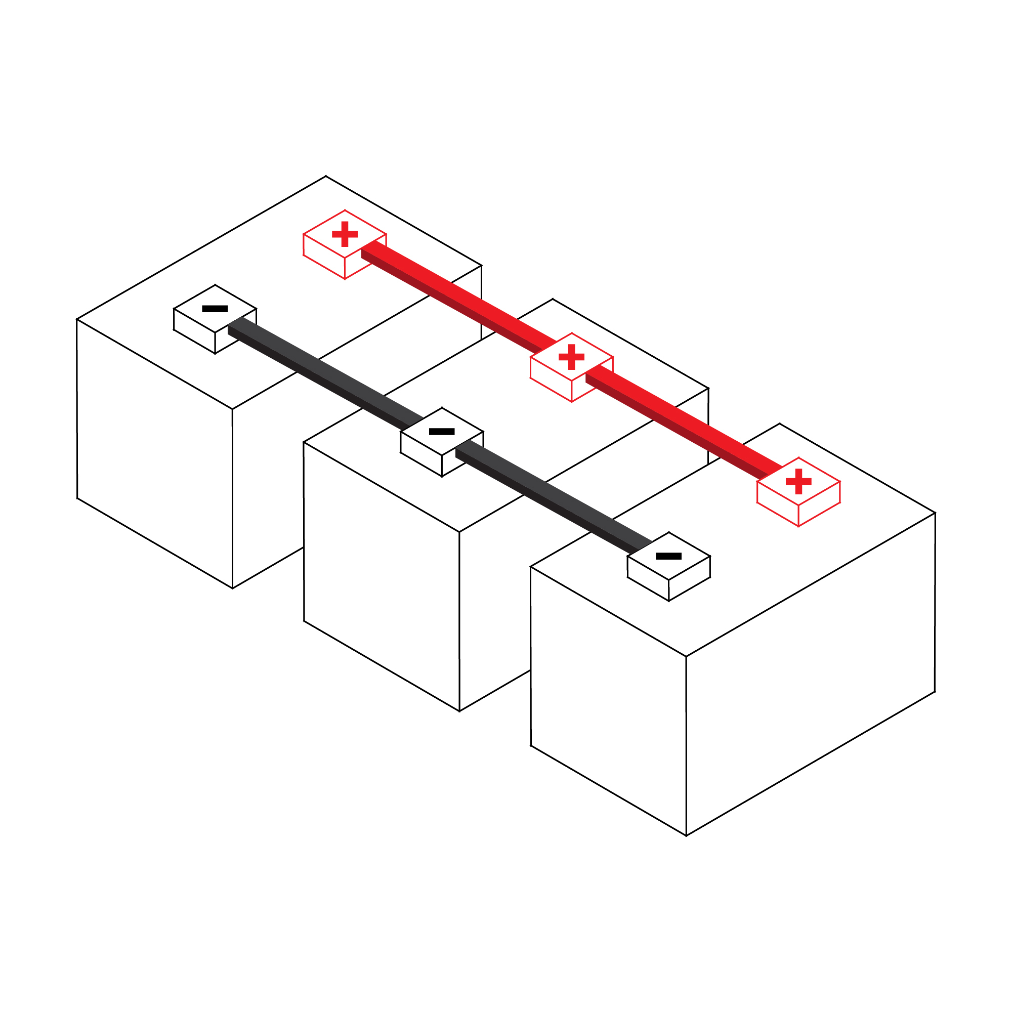
Wired In Series
Another way to wire your 12v batteries is "in series." This simply means that the negative terminal of one battery connects to the positive terminal of the next battery in the series, with the positive and negative terminals of the first and last batteries in the series being connected elsewhere in the system to complete the circuit, such as a converter.
The advantage of an in-series circuit is the opposite of the in-parallel circuit. In other words, an in-series circuit increases your voltage while keeping your amperage the same. If we used our previous example of two 12v DC batteries with 10 amp hours each and wired them in series, we would get a total of 24 volts DC at 10 amp hours.
Regardless of the wiring setup, RV batteries are usually connected to multiple things:
- A 12v power source, such as a vehicle alternator or a solar power system. The power source charges the batteries. If the RV is equipped with a solar power system, the power will be generated at the solar panel and flow to the solar controller, then flow to the 12v fuse box and batteries.
- A 12v DC fuse box or control panel. This regulates and directs the flow of 12v power to and from various appliances. For example, it can direct 12v power from the batteries to your 12v lighting to power them or direct 12v power from your converter to your batteries to charge them.
- A 12v DC to 120v AC inverter. This inverts the 12v power coming from your batteries, changes it to 120v AC power, and then sends that 120v power to your AC power circuit breaker and other appliances.
- An AC to DC power converter. This draws power from your 120v AC power sources and converts it to 12v DC power. Then, it sends that 12v DC power to your 12v fuse box to power your 12v appliances. In some cases, the converter may be connected directly to the 12v batteries to charge them, while the batteries themselves are connected to the 12v fuse box.
The 120v AC System
The 120v AC system in an RV or camper is used for a variety of appliances that need a bit more juice than 12v DC appliances. These appliances can range from things like an air conditioner or a microwave to providing power to your 120v outlets.
Thankfully, you generally don't have to mess around with batteries for your 120v system, as most campers and RVs will have their AC power system already installed from the factory. But, if you decide you need to make some modifications or repairs, it may be helpful to know how a basic 120v AC system works.
- Your AC power system draws power from an external source, usually via shore power or a generator.
- The power drawn from the AC power source then flows to the 120-volt fuse box, which then directly distributes the power to various appliances like your air conditioner, microwave, and outlets.
- The 120-volt fuse box may also direct that power to an AC to DC converter, which will convert the 120v AC power to 12v DC power, then direct that 12v power to your batteries or 12v fuse box.
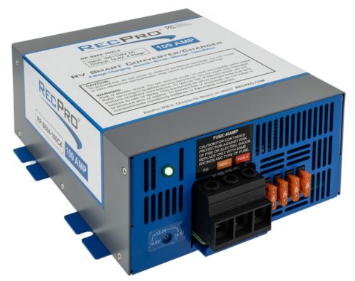
Wiring Converters and Inverters
Converters and inverters are two of the most commonly replaced parts of an RV or camper electrical system, whether for upgrade or repair. However, there is some nuance to wiring a converter or inverter correctly. For this segment, we'll use a 12v DC converter as an example, but the same information can be applied to inverters as well.
It may seem rather simple; just connect the positive and negative terminals of the converter to the terminals of the battery. While this is more or less true, the mistake that many people make is using the incorrect wire gauge or AWG. The wire gauge you'll need for your converter and batteries (or really any part of your electrical system) is determined by a few things:
- The maximum amperage the wire will need to carry between the connected components is also known as a wire's carrying capacity.
- Example 1: A 45 amp converter connected to a 12v battery rated for 100 amp-hours. In this example, the actual amperage of the battery is somewhat irrelevant, as the amperage flowing to or from the battery largely depends on what it is connected to. In this case, we'll assume that the converter is the only thing attached to the battery, which would make our maximum amperage 45 amps.
- Example 2: A 10 amp fuse in the 12v fuse box connected to a 3 amp 12v light. In this example, the maximum amperage between these two components would be 10 amps.
- Example 3: A 30 amp fuse connected to both an air conditioner with a maximum amperage of 16 and a microwave with a maximum amperage of 10 amps. In this case, the maximum amperage is still 30, and both the air conditioner and microwave should use the appropriate wire gauge for that amperage.
- The round-trip distance between the connected components.
- The round trip distance between two components is the total length of wire needed to connect two components together.
- Example 1: A 12v converter connected to a 12v battery using 6 feet of wire for the positive terminals and 6 feet of wire for the negative terminals would have a round-trip distance of 12 feet.
- Example 2: An air conditioner connected to a 120v fuse using 8 feet of wire for the positive connection and 5 feet of wire for the negative connection would have a round-trip distance of 13 feet.
So, why are these important? The carrying capacity of a wire should match or exceed the maximum amperage of the system. Using a wire with a carrying capacity that is lower than the maximum amperage drawn in the system can cause the system to be unable to supply power correctly. It can even be dangerous, as trying to push too many amps through too small a wire can cause that wire to overheat or even melt.
The wire length, or round trip distance, is important to know because it can affect your voltage. No matter the type of wire or the material it is made with, they all produce some level of heat and resistance. Resistance, in particular, is what can cause your voltage to drop, as the longer a wire is, the more resistance it will offer and, thus, the more voltage you will lose.
Thankfully, the voltage drop can often be solved by using a thicker wire gauge, giving you a higher amperage capacity and allowing you to push more power through the wire. That's why it is sometimes a good idea to use a wire with a higher carrying capacity than the maximum amperage of the system.
Other somewhat less impactful factors to consider when looking for the right wire are:
- The voltage at the source (In RVs and campers, this is typically 12v DC or 120v AC)
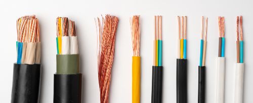
- The conductor material of the wire (copper, aluminum, etc.)
- Phases
- Insulation material and maximum wire temperature
- The ambient temperature of the environment the wire will be in
- The rated resistance of the wire (Ohms)
- Allowable voltage drop
How To Find The Right Wire Gauge
Once you know the maximum amperage between the components you want to connect together, such as a converter and your batteries, and the round-trip distance or length of wire you'll need, you can easily determine what gauge wire would be appropriate to use.
You can find numerous charts and calculators online where you can use the information outlined in the previous segment to determine the kind of wire that you will need. But, as a general rule of thumb, the higher the amps and the longer the round-trip length, the thicker the wire will need to be.
Here at RecPro, we've put together a 12v DC Converter Wire Gauge Chart for our RV converters, as well as a general 12v DC Wire Gauge Chart for general 12v wiring.
Speaking of wire gauge, why don't we talk a bit about it? The gauge of a wire refers to its thickness. This is commonly shown as a number by the acronym AWG, which stands for American Wire Gauge.
For example, a wire marked as 12AWG would be a 12 gauge wire.
When it comes to wire gauge thickness, a higher number will indicate a thinner wire size. In comparison, a lower number indicates a thicker wire size. So, a 12 AWG wire would be thinner than an 8 AWG wire.
Now You Know All About Trailer Wiring
Understanding and properly implementing trailer wiring is crucial for safety and road functionality. Following the guidelines outlined in this article, you can ensure that your trailer's electrical system is set up to meet your specific needs, whether you're towing a simple flatbed or a fully equipped RV. Proper wiring ensures that your trailer lights and brakes work correctly, protects your vehicle's electrical system, and enhances your overall towing experience.
By familiarizing yourself with the different types of connectors, wire color codes, and the specific wiring needs of your trailer and vehicle, you can avoid common issues and ensure your setup is reliable and efficient.
Always test your connections and address any problems immediately to avoid potential hazards while on the road. With the right tools, knowledge, and attention to detail, you can confidently wire your trailer, ensuring a safe and smooth journey every time.
Recent Posts
-
Custom RV Round Table - RecPro Video - Test
Custom RV Round Table - RecPro CUSTOMIZE HERE ► https://www.recpro.com/custom-rv-dinette-round-tab …May 28, 2026 -

Traveling to the RV Hall of Fame in Elkhart, IN
If you are traveling to Elkhart, IN to see the RV Hall of Fame, getting off the toll road at exit 96 …Nov 14, 2025 -

Best RV Air Conditioners of 2025: An Expert Guide From RecPro
Quick Answers Best overall RV air conditioner: RecPro 15K Quiet AC with Heat Pump (RP-AC3800) Best f …Oct 29, 2025 -

The Nuclear Nomads Expand Sofa with New Recliner Section Install
The Nuclear Nomads are a full time RV family living in south Florida. Andi and Joey value quality ti …Oct 24, 2025 -

Trailer Wiring Guide: How to Wire Your Trailer for Safety and Efficiency
Table of Contents 1. Common Types of Trailer Connectors 2. Trailer Wiring Diagrams: Color Codes and …Aug 20, 2024 -

How to Keep Your Pets Safe While Camping
RVing and camping are a great getaway from the hustle and bustle of work and the city and the day-to …Jul 02, 2024